What is SPI
The Serial Peripheral Interface
is a connection between a SPI master and one or more SPI slaves. There are four
signal lines: MOSI, MOSI, SCK and _SS.
A transfer of data is initiated by the master. It selects a slave with which to communicate.
Data are sent in both directions at once, bit by bit. The clock (SCK) controls the timing. A byte
is sent as a series of bits.
_SS : Slave Select from master to slave
A master can have several _SS lines. Usually, the program on the master, rather than
the SPI peripheral device controls the _SS lines. It sets the _SS line
for one of the slaves to LOW, activating it. The others should be kept HIGH, inactive.
In slave mode, the SPI hardware is activated by a transition on _SS.
SCK : Clock from master to slave
This line is used to synchronize the process of data transfer. There are two phases:
- The master places its bit on
MOSI and, simultaneously, the slave places its bit on MISO
- The master reads a bit from
MISO and, simultaneously, the slave reads a bit from MOSI
A program can configure if SCK is normally HIGH or LOW and which part of the signal change triggers
which of the phases.
When a program on the master transfers data, the hardware on the master sends a clock pulse for each bit to be
transferred.
MOSI : Master out, slave in. Data line.
When the clock signals that it is time to set up data, the master sends a bit to the slave over this line.
When the clock signals that it is time to read data, SPI hardware on the slave for which the _SS line is active will read the bit.
MISO : Master in, slave out. Data line
When the clock signals that it is time to set up data, the slave for which _SS is
active sends a bit to the master over this line.
When the clock signals that it is time to read data, the SPI hardware on the master reads this line.
On connected slave devices for which _SS is not active, the hardware keeps this
line at high impedance.
Sending a block of data
Microcontrollers such as the AVR chips and ARM chips made by Atmel have peripheral
devices embedded in the chip to handle SPI communications. Communications are initiated
by a program communicating with the device.
Here is the sequence of activities that occur:
- The program on the slave starts listening
The program on the slave device starts the SPI peripheral in slave mode. It loads one byte
of data to be sent as output. Then it waits for the slave's peripheral hardware to receive data from the
master.
- The program on the master selects a slave
The program writes to the slave's _SS as a normal digital output without
it's SPI hardware needing to be involved.
- The SPI peripheral on the slave detects its select line activated
The hardware on the slave device reacts to this change:
- Wake up
Some chips are designed to power up some of their circuits only when needed.
- Make MISO an output
When a slave device is not selected, the MISO signal should not
be an output. It must be configured as input or high impedance.
- Wait for clock signal
- The program on the master device starts up its SPI peripheral in master mode.
- Data exchange, repeat for each byte
When the SPI in the hardware gets a byte to send, it starts the clock. The master and slave
each send and receive a byte of data at the same time.
- The program on the master stops sending data.
It reaches the end of the block.
- The program on the master disables the slave by setting
_SS HIGH
- The slave peripheral shuts down. The program on the slave may take action when this occurs.
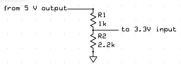
Connecting 5V and 3.3V
Some devices, such as Arduino Tian use 3.3 volts for I/O. Others, such as Arduino Uno use 5 volts
for I/O. A 3.3V output can be connected to a 5 volt input without problems. But going the other way
a voltage divider is needed.

